Dynamic Directions
A magic compass that points to your destination!
By Elizabeth Garner and Joey Horwitz
Demonstration Video
Introduction
Hi! We are Elizabeth Garner and Joey Horwitz, and for our Embeeded OS final project we built a direction finding compass. The project is in two parts: an embedded Raspberry Pi product and an Android app. The user inputs a destination into the app and then the Raspberry Pi controls a physical arrow which points to the target location. This is accomplished using the Google Places API, the phone’s GPS module, a magnetometer to measure the Pi’s orientation, and a stepper motor to control the arrow. At the end of the day we have a product which allows you to know where you’re going while still allowing you to wander. And, once you input the destination, all navigation can be accomplished without staring at a screen. It’s ideal for freeform exploration of new places :).
Project Objective:
The goal of our final project is to design a compass that points in the direction of a user-designated
destination. As this project rounds out the course, we wanted to incorporate both hardware and software
components into our design. As well, we looked to create a unique end product.
Our priority for this project was to process user input with our Raspberry Pi 4 to indicate towards the
destination. This allowed us to make design choices in the process for user experience and accuracy. In our
final design, we incorporated a motor, motor driver, magnetometer, Raspberry Pi 4, and battery power supply.
In terms of software, we developed an app that took destination input, sent current location, and communicated
with the Raspberry Pi.
Design
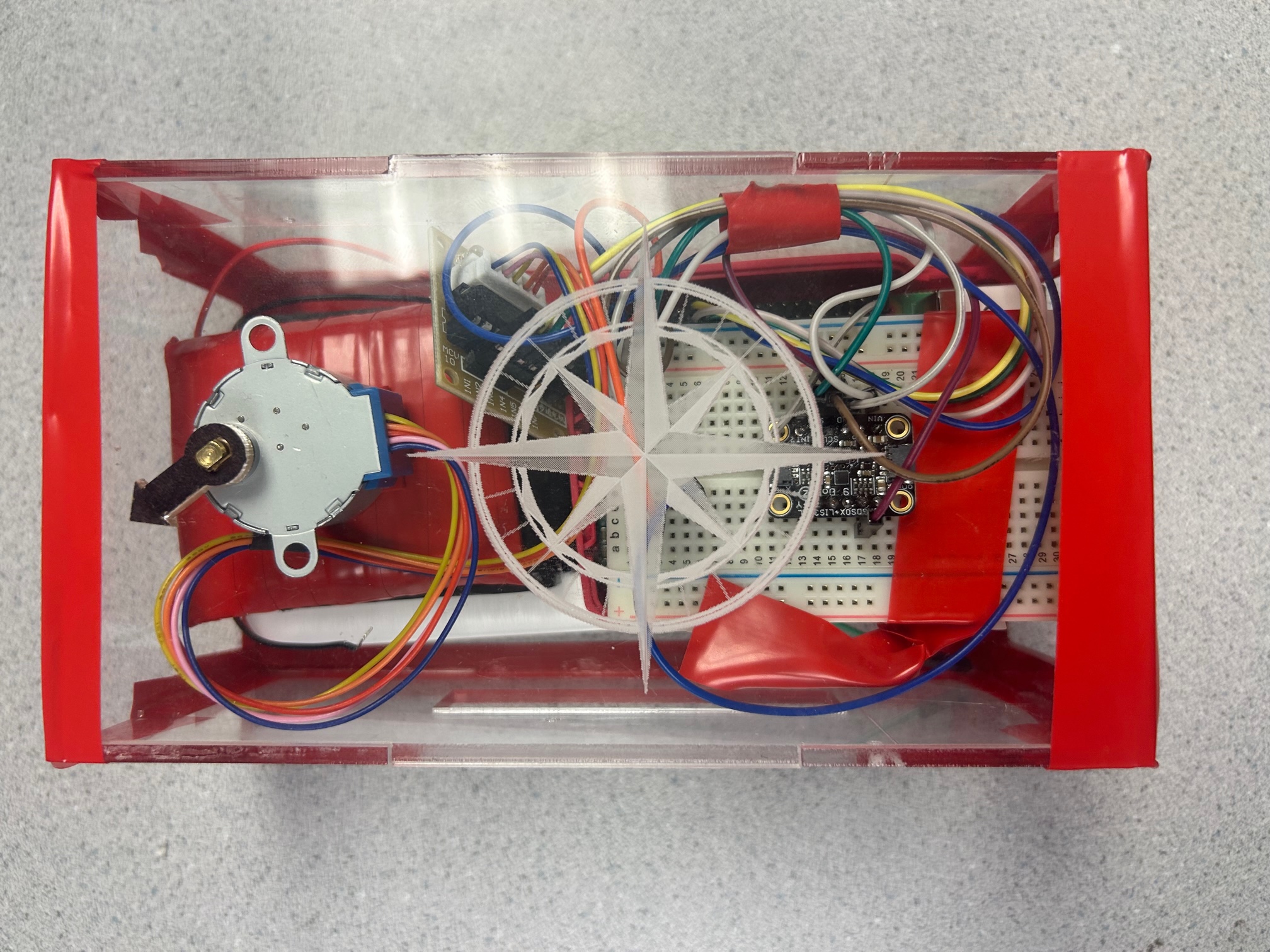
Hardware Design
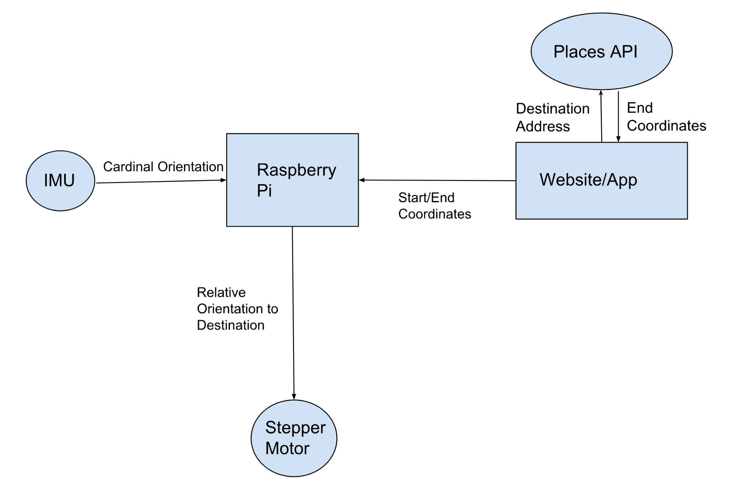
In our hardware design, we had a stepper motor, motor driver, magnetometer, Raspberry Pi 4, DC power supply, and phone battery power supply. Each of these followed a natural flow as data was received by the Pi and magnetometer, processed by the Pi, passed to the motor driver, and finally displayed with the stepper motor.
For our project, we selected a stepper motor as they are widely used for precise positioning. As well, the stepper motor we found had continuous rotation, allowing for our compass’ dial to move as a person holding the compass turns. Some motors on the market have 180 or 360 degrees of rotation. On such motors, the dial must rotate in the incorrect direction, impacting user experience. As well, the stepper motor we used came with a motor driver that was simple to use. We kept the included LEDs that lit up when the motor was turning to alert the user of any changes in direction.
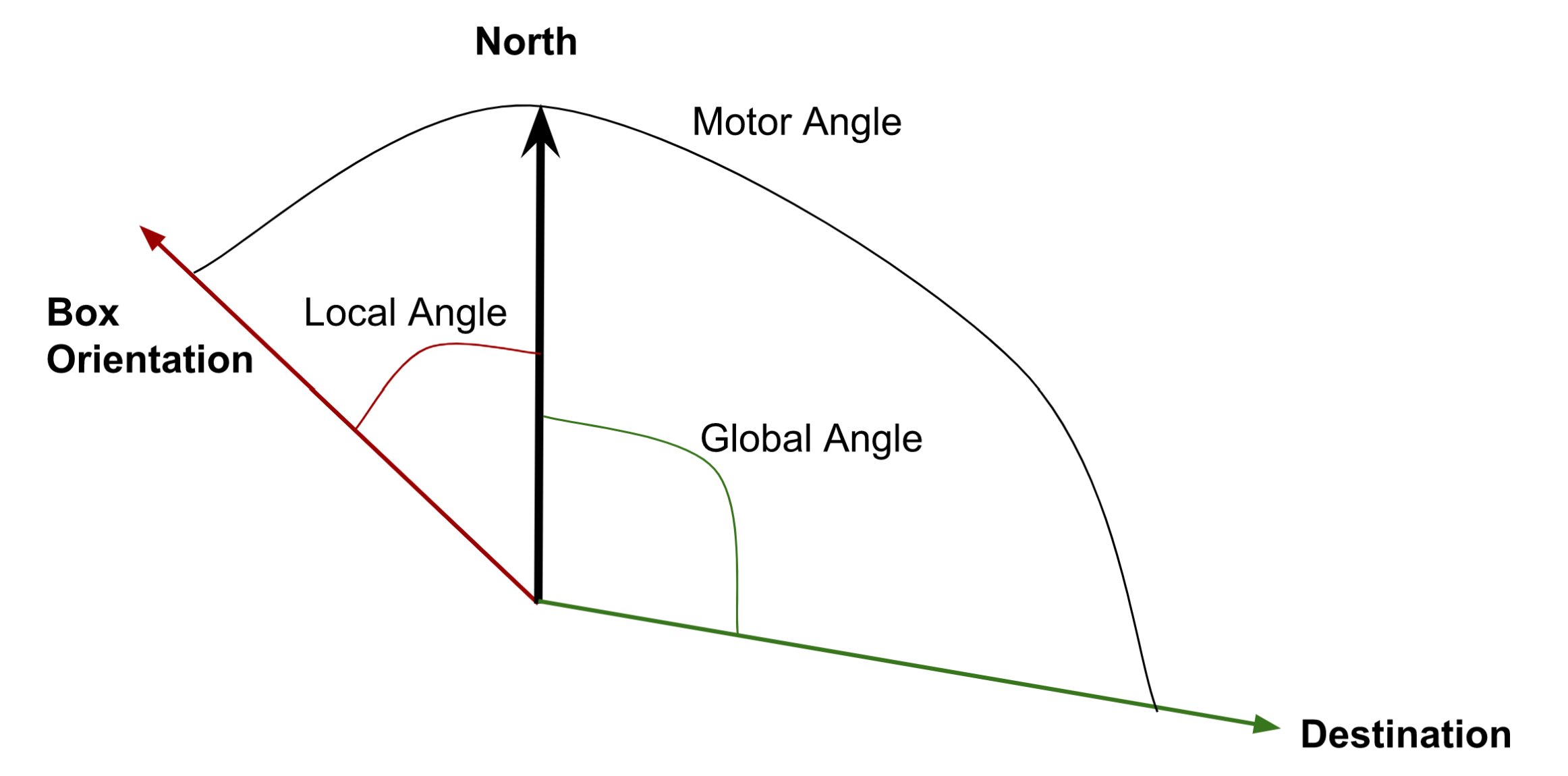
Next, we selected a magnetometer for our design to capture the angle of our compass. Since we could calculate the angle between the current and destination coordinates, we needed to know our angle relative to North to incorporate with this “global” angle. We called our box’s angle calculated from the magnetometer our “local” angle. This was important to keep track of at all times as the compass dial would need to compensate for the user not pointing in the same direction as the destination from their current location.
Since magnetometers measure the magnetic field around them, they can pick up noise from surrounding materials. This meant that while we were in the lab, we needed to be careful of what was happening around us and acknowledge that there would be noise. We discussed using a Kalman filter to help with the noise, but ultimately decided not to. We found that the noise within the lab from the nearby projects was less than expected and that the user could still get clear directions from the compass.
Upon first wiring our motor and magnetometer to our Pi, we kept our piTFT for debugging purposes. We had connected our magnetometer to an SPI pin used by the piTFT. In theory, there are multiple channels within this pin to send data in. On the code side, the Pi can look at data being received from a specific channel. This allows for multiple components to be wired to the same channel. However in practice, we were having issues with this. In the code, the channel number must be specified so the Pi knows which channel to be looking at. The channel the magnetometer was sending data over was changing as we were using it. We tried wiring the magnetometer to force it over a default channel, but we were still having issues with receiving the data consistently over this channel. In the end, we decided to remove the piTFT entirely as our final design did not include it.
For our power supply, we used two different types of batteries. Motors are notorious for creating issues with power and shorting connected components. This means that we need to be careful to have separate power and ground for our motor. As well, it was important to be able to easily wire in the battery pack. Instead of using a power cable like for the Pi, the motor batteries are wired into the circuitry. Our motor required 5-12V, which the Pi can technically support with its 5V output power pin. However, shorting our Pi with our motor’s inconsistent power needs was too risky. For our Pi, we used a phone power bank. The Pi conveniently has a micro USB port for power that regulates power for any surges. This saves our Pi from being shorted from our power supply. A Pi’s power pins, however, do not have such power protection.
Software Design
App Design
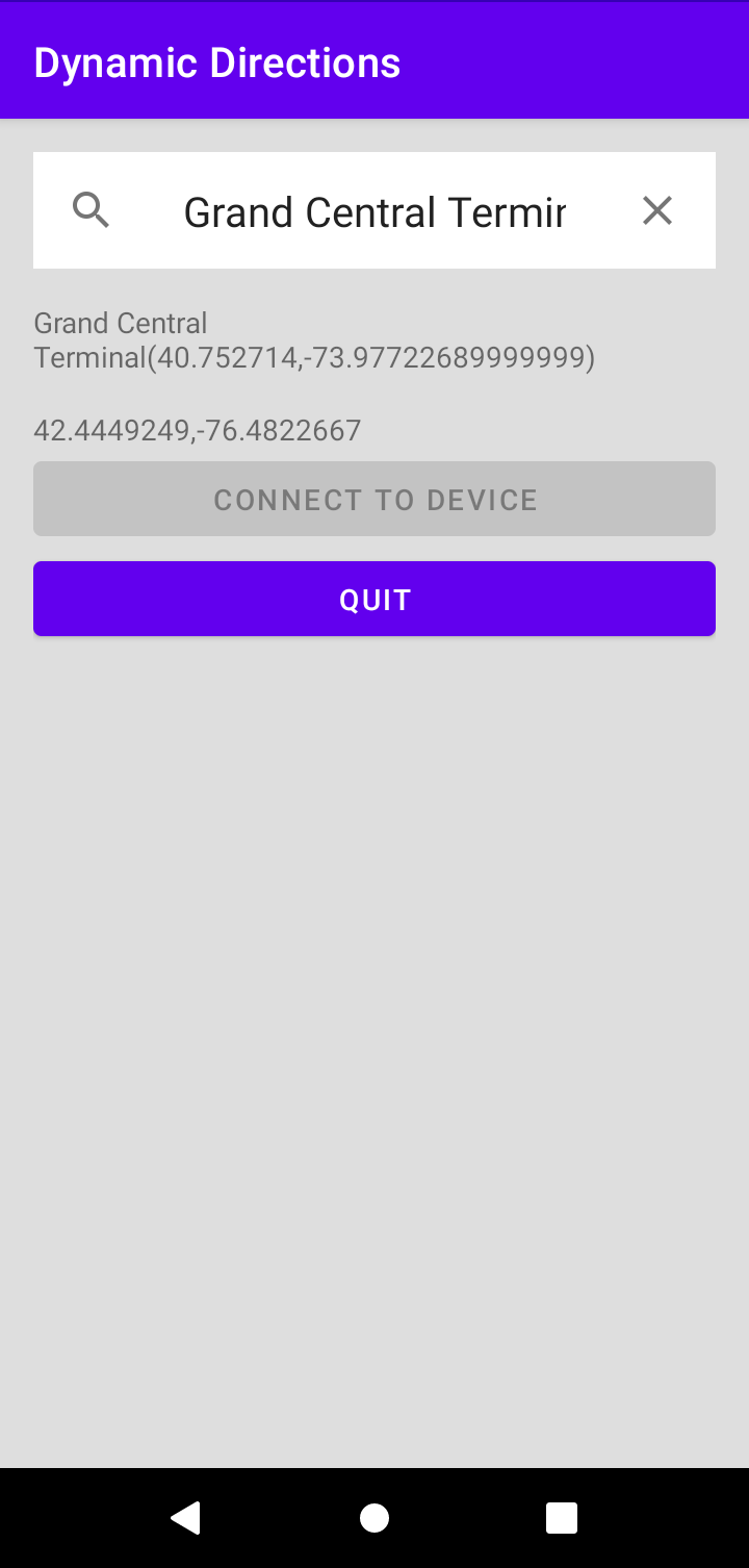
We designed the Android app using Kotlin with Android studio. The main page handles both of our key functions: allowing the user to enter a destination and finding the user’s current GPS coordinates. To help us find destination coordinates, we employed the Google Places API and Google Places Autocomplete widget. The autocomplete widget is a pre-built module that offers place suggestions to a user while they type. When the widget is initialized we also initialize a callback function for place selection, so that when a user taps on a desired location the longitude and latitude of that location will be stored for use with the Raspberry Pi. Then, when the Pi initializes a connection and requests destination coordinates, these autocomplete coordinates will be sent over. The app also prints the location name and coordinates to its screen. Both the autocomplete functionality and coordinate fetching require a web connection to the Google Places API, for which we obtained an API key.
To monitor the user’s current GPS coordinates we established a thread that works as a repeating timer which polls the GPS once a second. On every timed awakening the thread checks for location permissions, requests the location, and then executes a callback function which both stores the location for TCP and displays the coordinates to the screen.
Aside from these two core functions, we included two buttons in our app. The first was labeled “Connect to Device” and triggered the creation of our TCP server connection. The server is initialized as a runnable class and is told to begin listening. Then, when a request from the Pi comes in, the server will be able to respond with the current and destination locations obtained through the core elements of the app. The other button is called “Quit”, and it is used to instruct the Pi to return the compass to its home position and to stop requesting data, as the user is no longer using the app.
Socket Programming
An essential aspect of our design included sending and receiving data between our Android app and the Raspberry Pi. Initially, we tried to send information over a Bluetooth connection. Bluetooth does not require a router connection and allows the device to be taken anywhere. We were able to create a connection between the Pi and the Android phone, however, we could not utilize this connection within our Android app. There is not a large network of information available online on how to write code to send information from an Android app via Bluetooth or how to receive it on the Pi side. This made a Bluetooth connection difficult to work with. After a number of attempts, we decided to instead follow previous class projects and use TCP.
Although TCP connections require a router and for the internet to be accessible at all times, we found much more information online. As well, we saw past projects for this course using a TCP connection to send and receive information between Android and the Pi. First, we set up a connection using Python between the Pi and a laptop. This allowed us to experiment with example code and understand how socket programming works. At this point, we decided to switch from Native Script to Kotlin for our Android app. Since Kotlin is more similar to Java than Python, we set up a connection between a laptop and the Pi using a combination of Java and Python. The Pi was going to run on Python, so we kept that side of the connection in Python. On the laptop side, we moved from Python to Java. Finally, we were able to write a socket server in Kotlin.
Another design choice for socket programming was making the Pi a client and the app a server. Initially, we had the Pi as a server and the app as the client. However, a client polls information from the server. Instead of the app pushing information to the Pi, we wanted the Pi to request information from the app. This allowed for simpler code on both sides. Additionally, we made the Pi sit and wait for a connection, instead of looking and immediately closing out. We felt that this was more natural for the user as the user could begin sending information whenever they wanted.
IMU Magnetometer Angle
A magnetometer sends acceleration, gyro, and magnetic information to the Pi. For our design, we needed the magnetic information from the magnetometer. Since the Earth has its own magnetic field, the magnetic information allows us to calculate the angle relative to polar North. Using trigonometry, we were able to calculate this angle from the given data. This gave us our “local” angle.
Global Bearing Calculation
Next, we needed to determine the “global” angle of the compass. Initially, we used the longitude and latitude coordinates with numpy.arctan2, although this gave inconsistent results. After some research, we learned about bearing angles. Since the Earth is not flat, we must take its curvature into account when determining the angle between two coordinates. To account for this, we found a library called Geodesic that allowed us to easily calculate the bearing or “global angle” of travel which goes towards our destination.
Drawings
Module Overview
Angle Calculation
Testing
The main aspect of our project that required rigorous testing was combining our local and global angles. Since this was the summation of our project, any bugs at this point revealed themselves. Upon full assembly, we sent our compass a location North, South, East, and West of our position. We then compared the dial’s angle to Google Maps. After some tweaking, we were able to successfully point to North and East locations. However, we found our compass struggling greatly with pointing South. It became apparent that we had issues with our math. Our compass movement and speed worked well. Additionally, we could turn our compass body while it pointed toward a Northern destination and watch it compensate for its new local orientation.
After reviewing our math, we decided to switch to a library for bearing angles described above. We selected this library due to its information available online and ease of use. Since it was the final step of our project, we spent many lab sessions checking and fixing our angles. We added many print statements to display the current coordinates, destination coordinates, local angle, and global angle. Since we found ourselves going back and forth between different trigonometric representations of bearing or global angles, we opted for a library. Since there was online evidence that the library gave consistent and accurate results, we decided to utilize it.
Over the course of this project, we spend multiple lab sections testing our angles. This was the most noticeable aspect of the project to test as other portions either worked or they did not.
Result
Our magic compass was successful. Our objective was to design a compass that points in the direction of a user-designated destination. We were able to successfully read user input text, utilize a web API, transmit current and destination location information, read direction from a magnetometer, process this data, and see the physical results with a stepper motor to control a compass dial.
One major change we made was switching from Bluetooth to TCP connection. We were unable to send and receive information over a Bluetooth connection from the app to the Pi. Although Bluetooth took time to debug and work on, we learned about app coding and were able to better flush out our final design. It was important for us to understand our own priorities and work through a large obstacle. Despite the Bluetooth hiccup, we were able to accomplish our final goal and work through challenges. The final design was compact and efficient.
If we were to do this project again, we would have switched the coding language we were writing in earlier. Since only one partner had any experience with app development, we stuck with what we knew. Writing an app is daunting and takes time to learn about. As well, there is only so much information available online for each specific project type, making it challenging to branch out.
As a final project, the magic compass was an appropriate engineering design problem. Bringing together hardware and software components to create a functional device was rewarding. We were able to come to the lab with an idea and prior knowledge from the course projects and walk out with a working prototype. As well, the project kept the spirit of the course and aligned with past work to further our education in the intersection of hardware and software project design.
Future Ideas:
While we were satisfied with the outcome of our project, there are several features that we would have liked to add with more time. First, the cardinal orientation of the product is currently determined purely with a magnetometer. This worked better than we expected, but it is still noisy and susceptible to magnetic interference from nearby electronics and power sources. The magnetometer we are using is part of a 9 DoF IMU which also includes a gyroscope and accelerometer. If we applied a sensor fusion technique such as a Kalman filter to these three sensing modules then we could obtain a more accurate and stable measurement of orientation. Second, there are several ways we could expand how the user enters their desired destination. For example, we could attach a microphone to the Raspberry Pi module and employ text-to-speech technology to obtain a destination, effectively cutting out the smartphone. Another option would be attaching a map to the app and allowing users to tap on locations to select them as destinations. Third, it might be advantageous to the user to add a display to the product that presents the distance remaining between the person and their destination. To maintain the screen-free aesthetic of the product the display would need to be implemented as a set of dials.
Work Distribution

Project group picture

Elizabeth
emg229@cornell.edu
Oversaw TCP exchange, magnetometer interfacing, and circuitry design. Also took the lead on managing the project and fulfilling project update reports.

Joey
jah569@cornell.edu
Focused on Android development, stepper motor control, and fabricating the physical box. Also drove ideation of the product and its desired behavior.
Parts List
- Raspberry Pi 4 - $35.00
- Android Note 6 Phone - already possessed by Joey, price unknown
- 28BYJ-48 DC 5V Stepper Step Motor + ULN2003 Driver - $6.99
- Adafruit LSM6DSOX + LIS3MDL - $19.95
- Clear acrylic box with custom raster - Laser cut from CMC scrap material
- Protoboard, tape and wires - Provided in lab